Воздушный клапан – DMN Westinghouse
Теория и практика
Воздушный клапан – это пневматическая задвижка (пневмозадвижка) или пневматический тормоз, который был придуман Джорджем Вестингаузом еще в 19 веке, и им был получен патент (5.03.1872) на поистине гениальное устройство, которое использовалось при торможении поездов. Торможение, которое обеспечил Вестингауз, для того времени было просто уникальным и позволило намного увеличить скорость движение составов того времени.
Воздушный клапан того времени использовал сжатый воздух чтобы давить на поршень в цилиндре, который был соединен с тормозной колодкой трущейся о колесо. Весь воздух для поршня поставлялся через систему труб (тормозную магистраль), идущую через все вагоны, чтобы воздействовать на каждое колесо.
Современные воздушные клапаны
Воздушные клапаны начали бурно развиваться с появлением электричества, еще их называли электропневамтические. Главное премущество таких агрегатов было – отсутствие необходимости прокладывать воздушную магистраль через весь контур, а достаточно было поставить помпу, насос или пневматический нагнетатель. Современные пневматические тормоза и воздушные клапаны имеют значительные качественные конструкционные изменения, однако, базовый принцип их был заложен уже более 100 лет назад.
Воздушные клапаны (пневмозадвижки) DMN- Westinghouse
Шаровый воздушный клапан BTD
Высококачественный воздушный клапан BTD, с рабочим давлением от 0,5 до 6 бар, может использоваться при температурах от -25°С до 80°С градусов. Обладает чугунным корпусом. Приводом для пневмозадвижки BTD должен служить поворотный пневмоцилиндр двойного действия.
|
Размеры воздушного клапаны BTD |
65 |
80 |
100 |
125 |
150 |
200 |
250 |
|
Расход воздуха (литр)/ давление |
12,3 |
12,3 |
21,5 |
36,3 |
36,3 |
50 |
88 |
Класс защиты воздушного клапана — IP66, подробности – BTD
Воздушный клапан FDV
Поворотный распределительный воздушный клапан FDV обладает чугунным корпусом и выдерживает давление до 10 бар, при рабочих температурах от -30°С до +70°С. Среднее рабочее давление составляет 6 бар. Обладает цилиндром двойного действия в соответствии со спецификацией ISO 6431 с регулируемыми звуковыми пневматическими демпферами и магнитными поршнями.
|
Размер воздушного клапана FDV |
50 |
65 |
80 |
100 |
125 |
150 |
200 |
250 |
|
Расход воздуха при среднем давлении в 6 бар на литр/1 включение |
0.35 |
0.4 |
0.7 |
0.7 |
0.95 |
1.1 |
2.75 |
2.75 |
Воздушный Т-образный клапан FVV
Изготовлен из серого чугуна по DIN 0.6025 GG 25, алюминия и высокосортной стали, использование при сжатом воздухе до 10 бар, при условии прохождения фильтра, как с маслом, так и без, при температурах от -20°С до +95°С.
|
Размеры воздушного клапана FVV |
50 |
65 |
80 |
100 |
125 |
150 |
200 |
250 |
|
Расход воздуха при 6 барах литр/1 включение |
0.65 |
0.8 |
1.6 |
1.75 |
3.15 |
3.25 |
8 |
8 |
Описание остальных воздушных, роторных клапанов, дивертеров можно найти в разделе DMN-Westinghouse. Отправив запрос с формы на сайте мы предоставим Вам список поставщиков оборудования
Valve Cooling
It is obvious that the exhaust valve runs hotter than the inlet valve because the exhaust valve is always in contact with the hot gases while the inlet valve is somewhat cooled by the incoming fresh charge. The exhaust valve may actually become red hot during a short period of operation. The valve face is hottest and the valve stem is the coolest part of a valve.
![What is engine valves? types, working, mechanism [explained]](https://okz-rybinsk.ru/wp-content/uploads/2/6/4/264868c2a6b68b4dedfb228dc51407d1.jpeg)
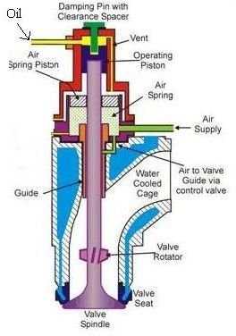
The valve stem passes heat to the valve guide and the valve face passes heat to the valve seat, and this helps to keep the valve cool. To provide adequate cooling, the cylinder head must be designed so as to permit good water circulation around the critical areas of the valve.
If the valve face fits properly on the valve seat and completely closes the combustion chamber, there will be no loss of compression and power.
In spite of this, the proper valve seating also provides full face contact with the valve seat through which more heat transfer can take place. Uneven contact may cause a valve to run several hundred degrees hotter than normal, which will shorten the valve life.
Eccentric Rocker Arm
The eccentric rocker arm automatically compensates for the difference in valve-tappet clearance. It consists of a conventional rocker arm modified to hold an eccentric by means of a slot and pin.
The plunger and spring control the piston of an eccentric. The plunger is activated by the spring and by oil pressure from an orifice in the rocker arm.
When the engine valve is closed (cam on the low side), the eccentric under the action of spring and plunger moves to take up any clearance, in the valve operating the train. As the cam rotates to open the valve, the plunger and spring absorb any shock produced by this movement. When the cam is on the upside, the valve is completely open.
Конструкция
Прототип XF2Y-1 в полёте
Прототип имел треугольное крыло, водонепроницаемый корпус и гидролыжи для взлёта и посадки на глиссировании. В неподвижном состоянии или на малой скорости самолёт удерживался на воде за счёт водоизмещающего корпуса, при этом задняя кромка крыла касалась воды. На взлётном глиссировании, по достижении скорости 16 км/ч гидролыжи опускались вниз, поднимая корпус над водой: после взлёта они подтягивались к корпусу.
В качестве двигателей предполагались два турбореактивных форсажных Westinghouse XJ46-WE-02 с воздухозаборниками, расположенными высоко над крылом, во избежание попадания воды. Двигатели не были готовы к испытаниям, и прототип полетел с двумя ТРД Westinghouse J34-WE-32, которые обеспечивали лишь половину проектной мощности.
На прототипы устанавливались различные конфигурации лыж. Первый самолёт был оснащен одной лыжей (что оказалось наиболее удачной схемой), второй прототип- двумя. Устанавливались и другие варианты конфигурации лыж.
What is Engine Valves?
Contents
A valve is a device to close and open a passage. Engine valves are devices that are used in internal combustion engines to allow or stop the flow of fluid or gas from cylinders or combustion chambers during the engine while the engine is operating.
These are also known as check valves which are used for air injection in vehicles as part of emission control and exhaust gas recirculation systems. Engine valves are commonly employed in every type of combustion engine such as gasoline, diesel, kerosene, natural gas, or propane.
In motor vehicle engines, two engine valves are used for each cylinder-an inlet (or intake) valve and an exhaust valve. So, this article helps you to understand the different types of engine valves along with their functions and operation in combustion engines.
Inlet Valve
Fuel is allowed to the cylinder by the inlet valve. When closed, the valve seals the combustion space tightly. The valves are usually made of austenitic stainless steel which is a corrosion and heat-resisting material. Inlet valve is subjected to less heat is usually made of nickel-chromium alloy steel.
Exhaust Valve
The burned gases escape by the exhaust valve. The exhaust valve is usually made of silichrome steel which is an alloy of silicon and chromium with unusual resistance to heat.
The valves used in car engines are termed poppet or mushroom valves. The head of the valve has an accurately ground face with enough margin left to avoid a thin edge.
The angular face is ground on the valve head to make an angle of 45° or 30° to match the angle of the valve seat in the cylinder head. Spring retainer lock grooves are provided at the end of the valve stem.
Read also: List of Car Engine Parts: Its Function (With Pictures)
Sodium Cooled Valve
In many heavy-duty engines, sodium-cooled valves are used. A sodium-cooled valve has a hollow stem, which is partly filled with metallic sodium. Sodium melts at 97’5°C.
Thus, at operating temperatures the sodium is liquid. When the engine is running, the valve moves up and down, the sodium is thrown upward into the hotter part of the valve.
It absorbs heat, which is then given up to the cooler stem as it falls down in the stem again. This action keeps the valve head cool.
Sodium cooled valve runs as much as 100°C cooler than a solid stem valve of similar design under the same operating conditions. This means a sodium-cooled valve has a longer life. But its use requires more care.
If the hollow stem of the sodium-cooled valve is cracked or broken, it is potentially dangerous. Sodium bursts into flame in contact with water. It causes a deep and serious burn on the skin, As long as sodium is safely in the valve stem, there is no danger.
Cylinder block
The 318 Magnum engine has a cast-iron block with a five-bearings crankshaft supported system. The cylinder bore is 99.3 mm (3.91 in), piston stroke is 84.0 mm (3.31 in) and the compression ratio rating is 9.1:1. This motor has aluminum alloy pistons with two compression and one oil control rings, forged steel connecting rods, and nodular iron crankshaft. The crankshaft main journal diameter is 63.5 mm (2.5 in) and the crankpin diameter is 53.0 mm (2.08 in).
| Cylinder block | ||
| Cylinder block alloy | Cast-iron | |
| Compression ratio: | 9.1:1 | |
| Cylinder bore: | 99.3 mm (3.91 in) | |
| Piston stroke: | 84.0 mm (3.31 in) | |
| Number of piston rings (compression / oil): | 2/1 | |
| Number of main bearings: | 5 | |
| Cylinder inner diameter (standard): | 99.314-99.365 mm (3.91-3.912 in) | |
| Piston skirt diameter (standard): | – | |
| Piston pin outer diameter: | 24.996-25.001 mm (0.9841-0.9843 in) | |
| Piston ring side clearance: | Top | 0.038-0.076 mm (0.0015-0.003 in) |
| Second | 0.038-0.076 mm (0.0015-0.003 in) | |
| Oil | 0.060-0.210 mm (0.0024-0.0083 in) | |
| Piston ring end gap: | Top | 0.254-0.508 mm (0.010-0.020 in) |
| Second | 0.254-0.508 mm (0.010-0.020 in) | |
| Oil | 0.254-1.270 mm (0.010-0.050 in) | |
| Connecting rod small end diameter: | 24.940-24.978 mm (0.9819-0.9834 in) | |
| Crankshaft main journal diameter: | 63.487-63.513 mm (2.4995-2.5005 in) | |
| Crankpin diameter: | 53.950-53.975 mm (2.124-2.125 in) |
Types of Engine Valves
There are 3 different types of engine valves as follows:
- Poppet valve
- Sleeve valve
- Rotary valve
- Reed valve
#1 Poppet Valve
It is also known as a mushroom valve because of its shape. It is used to control the timing and quantity of gas flow into an engine. This is the most widely used valve in an automobile engine. The poppet valve is given the name because of its motion of popping up and down.
It consists of a head and a stem. The valve face usually with an angle of 30° to 45° is ground perfectly, since it has to match with the valve seat for perfect sealing.
The stem has a spring retainer lock groove and its end is in contact with the cam for up & down movements of a valve. In exhaust, a pressure differential helps to seal the valve. In intake valves, the pressure differential helps open them.
#2 Sleeve Valve
The sleeve valve as the name implies is a tube or sleeve that fits between the piston and the cylinder wall in the cylinder of an internal combustion engine, where it rotates/slides.
Ports on the side of the sleeves come into alignment with the cylinder’s inlet and exhaust ports at the appropriate stages in the engine’s cycle.
The inner surface of the sleeve forms the inner cylinder barrel in which the piston slides. The sleeve is in continuous motion allowing and driving out the gases by virtue of the periodic coincidence of port cut in the sleeve with ports formed through the main cylinder casting.
Advantages
- These valves are simple in construction and are silent in operation.
- There is noise because there are no noise-making parts like valve cams, rocker arm, tappets valves, etc.
- Sleeve valve has less tendency of detonation. Cooling is very effective as the valve is in contact with water jackets.
#3 Rotary Valve
There are many types of rotary valves. The figure shows the disc-type rotary valve. It consists of a rotating disc that has a port. While rotating, it communicates alternately with the inlet and exhaust manifolds.
Advantages
- Rotary valves are simple in construction and are manufactured at cheaper costs.
- They are suitable for high-speed engines.
- These valves have fewer stresses and vibrations.
- Rotary calves perform smooth, uniform, and noise-free operations.
#4 Reed Valve
Image: Wikipedia
These are a type of check valve that opens and close the flow of fluid in the same direction under varying pressure on each face. It is consists of a mechanical bar hinged at one end that covers the passage and allows air or charge to flow in only one direction.
This valve is placed such that the suction pressure opens the inlet valve and closes the exhaust valve. And the exhaust pressure closes the inlet valve and opens the exhaust valve. These are usually installed in two-stroke engines.
Read Also: What is the function of Crankshaft? Parts, Types, Uses
Chrysler 318 V8 Engine Specifications
The Chrysler 318 originally came as a flat-tappet 90-degree OHV (overhead valve) V8 engine. The first LA Chrysler 5.2 engines had a compression ratio of 9.2:1, which fell to 8.6:1 during the SMOG years of the 1970s. At introduction, the 318 had 230 horsepower at 4400 RPM and 340 LB-FT of torque at 2,000 RPM.
ENGINECHRYSLER 318 (LA 5.2L) SMALL BLOCKMANUFACTURERCHRYSLERYEARS PRODUCED1967 TO 1991DISPLACEMENT317.5CI (5.2-LITERS)CONFIGURATION90° OHV 2-VALVE V8FUEL TYPEGASOLINECOMPRESSION RATIO9.2:1 (1967)FIRING ORDER1-8-4-3-6-5-7-2BORE3.9062 INCHES (99.2 MM)STROKE3.312 INCHES (84.1 MM)HORSEPOWER (1963)230 HP (171.5kW) (1967)TORQUE340 LB-FT (1967)GAS MILEAGE12-20 MPG (EST)
Horsepower and torque also fell off during the 1970s to 145-155 HP at 4,000 RPM and 260 LB-FT at 1,600 RPM. The LA 318 was designed to use regular gasoline in its common 2-barrel (2BBL) carburetor configuration and its 4-barrel (4BBL) configuration. Fuel-injected models also used regular gasoline.
The engine is a pushrod V8 with a bore of 3.9062 inches and a stroke of 3.312 inches, which is the same as its A-Series predecessor.
Chrysler 318 History
The Chrysler 318 was introduced in 1967 (for model year 1968) as a mid-sized V8 offering in Chrysler’s LA (Light A) engine series. At the time, Plymouth had already offered a 318 cubic-inch V8 since 1957, and though functionally similar, the A-Series engine is not the same as the LA 318. The LA engine series design was very similar to the A-Series but around 50 pounds lighter.
The Chrysler 318 was manufactured primarily in Detroit, Michigan, at Chrysler’s Mound Road manufacturing facility. Like most brands at the time, the engine was also manufactured at other factories in Mexico and Canada.
The LA-Series engines, which were first introduced in 1964, became the backbone of MOPAR production and gained widespread notability. The 318 wasn’t as powerful as the 340 or the 360, but it was a formidable engine that saw widespread use in cars and trucks.
It’s difficult to draw a direct comparison with other brands, but the small block 318 engine was a reasonable alternative to the Ford 302 and the Chevy 305 in terms of power and application. However, power variations over the years certainly make this comparison arguable.
The Chrysler 5.2L was usually outfitted with a 2-barrel carburetor from the factory. However, some trucks and cars (such as many police models from 1978 onward) came with a stock 4-barrel Thermoquad or Quadrajet carburetor.
Over the years, the basic design of the LA 318 stayed fairly constant. There were a few available modifications (especially during the latter years of production), including available electronic throttle-body fuel injection (TBI) on the 1981-83 Chrysler Imperial.
The 318 used hydraulic lifters from its introduction, which reduced that signature tapping sound associated with older A-Series solid-lifter engines. Initially, the Chrysler 318 V8 was a flat-tappet engine, but it was upgraded to roller lifters beginning in 1985.
![What is engine valves? types, working, mechanism [explained]](https://okz-rybinsk.ru/wp-content/uploads/2/0/e/20e530646ca2f4800ab5e95040507b05.jpeg)
The original LA-Series Chrysler 318 engine was discontinued in 1991 and replaced with the heavily-modified Magnum 318.
Hydraulic Valve Lifter
It is very quiet in operation because it ensures zero valve tappet clearance. It automatically adjusts its length to compensate for differences in the valve. tappet clearance. Also, it usually requires no adjustment in normal service.
Its body consists of a cylinder and an oil reservoir. An opening in the body is connected with an oil pressure line from the engine lubricating system to supply the reservoir with oil. A plunger fits inside the cylinder so that its upper end contacts the bottom of the pushrod, and its lower end is supported by oil between it and the bottom of the cylinder.
When the valve is closed as at (a) (cam on the lower side), oil from the reservoir opens the ball-check valve and raises the plunger by passing between it and the cylinder bottom. This produces zero clearance between the lifter unit and push rod, and between the rocker arm and valve stem.
When the cam turns to lift the lifter as at (b) (cam on the upside). The ball-check valve closes to prevent the return of oil to the reservoir and causes the entire lifter unit to lift the pushrod to open the valve. Because the lift starts with zero clearance, the noise is reduced to a minimum.
As shown at (b) during the lifting operation, a certain amount of oil is allowed to leak between the plunger and the cylinder, which causes lowering of a plunger to produce clearance if the spring did not raise it again when the pressure on the plunger is relieved by the closing of the engine valve. This reopens the ball check valve, oil again comes beneath the plunger and the lifter is again set for zero clearance.
Read Also: What is Piston Pin? Working, Types, Parts, Advantages
Cylinder head
The cylinder heads are made of cats-iron. The engine has a single camshaft over-head valves. The camshaft is driven by a single timing chain. The intake valve diameter is 48.665 mm (1.916 in), the duration is 250° the exhaust valve diameter is 41.250 mm (1.624 in), the duration is 264°. The Chrysler 318 Magnum engine is equipped with hydraulic valve tappets.
| Cylinder head | ||
| Block head alloy | Cast-iron | |
| Valve Arrangement: | OHV, chain drive | |
| Head surface flatness | – | |
| Valves: | 16 (2 valves per cylinder) | |
| Intake valve timing | 250° | |
| Exhaust valve timing: | 264° | |
| Valve head diameter: | INTAKE | 48.665 mm (1.9159 in) |
| EXHAUST | 41.250 mm (1.624 in) | |
| Valve length: | INTAKE | 124.280-125.92 mm (4.8929-4.9575 in) |
| EXHAUST | 124.64-125.27 mm (4.9071-4.9319 in) | |
| Valve stem diameter: | INTAKE | 7.899-7.925 mm (0.311-0.312 in) |
| EXHAUST | 7.899-7.925 mm (0.311-0.312 in) | |
| Valve spring free length: | 49.962 mm (1.967 in) |
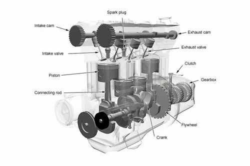
Types of Engine Valve Mechanisms
The valves are operated by cams mounted on a camshaft. The camshaft gets motion from the crankshaft. As the camshaft turns, the cam operates the valve.
According to the location of the valves, the valve mechanism is of two types:
- Valve mechanism for operating the valve in engine block (straight poppet valve).
- Valve mechanism for operating the valve in the cylinder head (overhead poppet valve).
Valve-Tappet Clearance
A slight clearance is kept between the valve tappet and the valve stem in the case of the straight poppet valve, and between the rocker arm and valve stem in the case of the overhead poppet valve. This is known as valve tappet clearance, and sometimes as valve lash. This clearance allows for expansion of the valve stem as the engine becomes heated.
If sufficient clearance is not given, the valve will not seat properly when the engine becomes heat, which will cause power loss and lifting of the valve. It is better to have more clearance than necessary rather than to have too little, in spite of the slight increase in noise of the valve mechanism.
The valve-tappet clearance depends upon the following factors:
- Length of the valve stem
- The material of the valve.
- The temperature at which the engine operates.
Chrysler 318 Applications
The Chrysler 318 was the “standard” V8 offering for many years and represented the upgraded economy-range engine option. Later, the 360 was typically the next level up, though the 340 was also popular in many vehicles.
The 318 was used extensively across the Chrysler coupe and sedan lineup. It was also used in cars by Dodge and Plymouth for decades. Dodge trucks were commonly equipped with the 318 and received a second TBI fuel-injection upgrade during 1988.
Heavier vehicles, such as commercial trucks and RVs, also came with the 318. This engine was used extensively in marine applications and found on everything from ski boats to small trawlers.
This Chrysler 5.2L engine was popular in police cars. After 1978, many police models came equipped with a 4BBL carburetor, though some vehicles (like 1980s Dodge Diplomat police cars) came with a basic 2BBL 318.
Which equipment should you choose?
Darts bars have house darts ready for you to use, but the weight and balance of these darts differ from place to place.
In order to stabilize your throw, we recommend that you get your own darts once you have gotten used to the game.
Darts equipment come in a variety of types and shapes, so you should actually practice a few rounds with the items when choosing. Choose the items that suit you or by the design you like.
Here we will provide a simple explanation of the different types available for each parts.
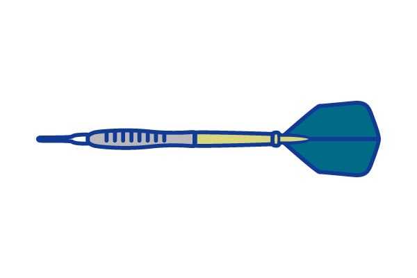
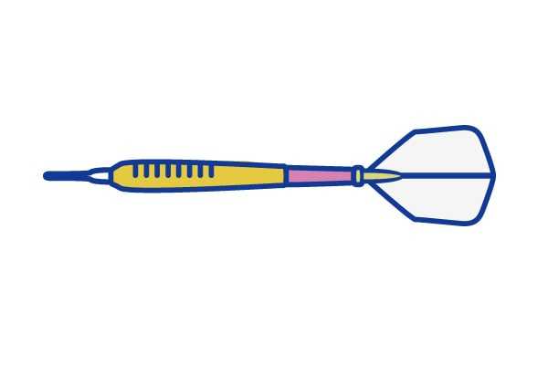
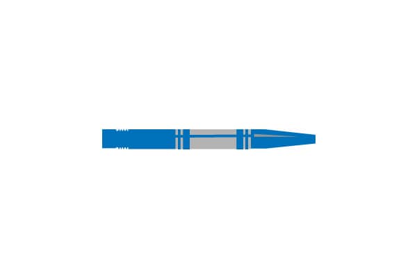
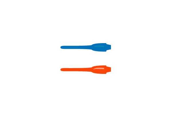
Barrels
The part of the dart that you grip. It is the most important part that will be the center of balance on the dart. Be sure to take your time and choose one that suits you!
The barrels mainly come in two materials, Brass and tungsten. For beginners we recommend the comparatively lighter brass types! For most players who are medium level or higher, we recommend the tungsten dart.
Brass darts
Mainly made of brass, these barrels are lighter and less expensive.
Since the barrel is thick, it is easy to grip for people with large hands and beginners.
Many of these types of barrels have a center of gravity positioned towards the front, making it easy to throw in a nice parabolic line.
Therefore brass darts are recommended for beginners.
Tungsten darts

These barrels are made of nickel and tungsten alloy. They are stronger, thinner, and heavier than brass.
As you improve your darts skills, you will want to land multiple darts in a small area such as the BULL in order to gain more points. If the barrel is too thick, your dart will go out of the board. So it is better to choose the thinner tungsten darts over brass darts.
Flight
If the flight is large, there is more air resistance, and that makes it easier to throw the dart straight without using extra force, so we recommend larger flights for beginners.
Larger size

With larger flights, there is increased air resistance, so you can easily throw darts in a stable manner.
Recommended for beginners.
Smaller size

Smaller flights are good when you want a sharp throw or want to aim for the same points.
Recommended for medium level players and higher.
Special shape

Specially shaped flight, such as the heart shaped ones each have their special characteristics. The cute shapes are perfect for girls.
You should try these once you’ve gotten used to the game.
Shaft
The longer the shaft is, the more stable the dart is, and you can throw the dart easily without extra force.
If the shaft is short, you can throw darts in a strong, sharp manner. The shaft is made of materials such as plastic and aluminum.
Medium type and long type
With longer shafts, you can easily hit where you aim without extra force. There are a variety of designs and color variations.
Short type and Extra short type
There are ones that are thick throughout, and ones that have a hole in the center to make them lighter. When attaching a shorter shaft, be sure to choose a smaller flight.
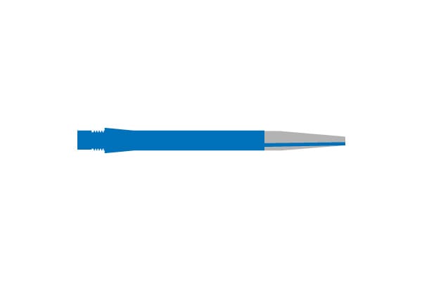
Tip
The tip is the part that sticks in the dart board. It is made of plastic. Expendable.
In order to reduce the weight, there are some designs with a hole. We recommend using different lengths and types!
Long size
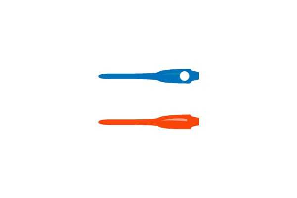
Longer the tip, it is easier to hit the board. So, the longer tip is recommended for beginners. Using the long tip will make the distance from the barrel long, for this reason this type is also recommended for advanced players aiming to hit the same target.
Short size
Since it is lighter than long types, it does not significantly affect the overall weight of the dart. Additionally, since it has a higher resistance that the long type, it is stronger. If your tip is easily broken, you should try this type.
Формула изобретения
1. Радиаторный клапан, имеющий шток, впускное отверстие, первое седло клапана, взаимодействующее с первым затвором, и второе седло клапана, взаимодействующее со вторым затвором, приводимым в действие штоком, причем оба седла клапана размещены параллельно друг другу за впускным отверстием и оканчиваются общим выпускным отверстием, характеризующийся тем, что имеется открывающая пружина (11), нагружающая первый затвор (7) в направлении от первого седла (6) клапана, в клапане предусмотрен упор (31), посредством которого шток (10») опирается на первый затвор (7), а в первом затворе (7) имеется отверстие (27), через которое ко второму затвору (9) может подаваться жидкость из впускного отверстия (4).
2. Клапан по п.1, характеризующийся тем, что первый затвор (7) связан со вторым затвором таким образом, что перемещение первого затвора (7) зависит от второго затвора (9).
3. Клапан по п.1, характеризующийся тем, что второй затвор (9) установлен с возможностью перемещения на определенное расстояние, прежде чем первый затвор (7) отойдет от первого седла (6).
4. Клапан по п.1, характеризующийся тем, что между вторым затвором (9) или связанными с ним деталями и первым затвором (7) или связанными с ним деталями находится пружина (20, 25), нагружающая первый затвор (7) по направлению к первому седлу клапана (6).
5. Клапан по п.1, характеризующийся тем, что первый затвор (7) и второй затвор (9) установлены коаксиально относительно друг друга.
6. Клапан по п.1, характеризующийся тем, что второе седло (8) клапана выполнено на первом затворе (7).
7. Клапан по п.1, характеризующийся тем, что второй затвор (9) имеет штифт (18) и установлен с возможностью действовать на первый затвор (7).
8. Клапан по любому из пп.1-7, характеризующийся тем, что второй затвор (9) установлен на клапанном штоке (10, 10′, 10»), который может быть приведен в действие снаружи.
9. Клапан по п.8, характеризующийся тем, что клапанный шток (10) выполнен в виде закрытой с одной стороны трубы, в которой установлена пружина сжатия (20), которая благодаря штифту (21), выступающему из трубы и установленному с определенным осевым зазором, нагружает первый затвор (7) в направлении закрывания.
10. Клапан по п.8, характеризующийся тем, что пружина сжатия (25) находится между первым затвором (7) и опорой (24), установленной на клапанном штоке (10′) с осевым зазором.
11. Клапан по п.8, характеризующийся тем, что пружина (30) установлена с зазором в ограничительном элементе (28) с возможностью воздействия на первый затвор (7) с силой, превышающей силу воздействия открывающей пружины (11), на протяжении части хода второго затвора (9).
![What is engine valves? types, working, mechanism [explained]](https://okz-rybinsk.ru/wp-content/uploads/0/4/f/04fdd4edcaaa26a8e642c9bf927ba3e8.jpeg)
12. Клапан по п.11, характеризующийся тем, что пружина (30) установлена в ограничительном элементе (28), крепящемся к клапанному штоку (10») с осевым зазором.
Разработка
Convair F2Y Sea Dart на глиссировании
Самолёт был разработан компанией Convair в рамках заказа флота (1948) на создание сверхзвукового перехватчика. В то время существовал скептицизм по поводу успешного использования сверхзвуковых самолётов на авианесущих кораблях (в частности, поэтому все корабельные самолёты этого периода были дозвуковыми). Проблемы виделись в большом разбеге и пробеге сверхзвуковых самолётов и их большой скорости посадки. Ряд решений этих проблем предполагал создание реактивного гидросамолёта-истребителя. По такой схеме был выполнен и проект самолёта F2Y Sea Dart.
Проект Convair был одобрен, постройка двух прототипов заказана в конце 1951. Ещё до полёта первого прототипа была заказана серия из 12 машин. Хотя на построенные самолёты не устанавливалось какого-либо вооружения, в перспективе планировалось вооружить самолёты четырьмя 20-мм пушками и неуправляемыми ракетами.
dart valve
Англо-русский словарь нефтегазовой промышленности . 2011 .
Смотреть что такое «dart valve» в других словарях:
Dodge Dart — Manufacturer Chrysler Corporation Production 1960–1976 Predecessor Dodge Lancer (For compact version) … Wikipedia
желонка со сферическим клапаном — — [http://slovarionline.ru/anglo russkiy slovar neftegazovoy promyishlennosti/] Тематики нефтегазовая промышленность EN dart valve bailer … Справочник технического переводчика
Chrysler LA engine — The LA engines are a family of pushrod OHV 90° V block gasoline engines built by Chrysler Corporation and factory installed in passenger vehicles, trucks and vans, commercial vehicles, marine and industrial applications from 1964 through 2003.… … Wikipedia
fish — fishless, adj. /fish/, n., pl. (esp. collectively) fish, (esp. referring to two or more kinds or species) fishes, v. n. 1. any of various cold blooded, aquatic vertebrates, having gills, commonly fins, and typically an elongated body covered with … Universalium
Fish — /fish/, n. Hamilton, 1808 93, U.S. statesman: secretary of state 1869 77. * * * I Any of more than 24,000 species of cold blooded vertebrates found worldwide in fresh and salt water. Living species range from the primitive lampreys and hagfishes… … Universalium
Muscle car — This 1966 Pontiac GTO is an example of a classic muscle car Muscle car is a term used to refer to a variety of high performance automobiles. The Merriam Webster definition is more limiting, any of a group of American made 2 door sports coupes… … Wikipedia
Plymouth Valiant — Infobox Automobile name = Plymouth Valiant manufacturer = Plymouth parent company = Chrysler Corporation production = 1960–1976 platform = A body layout = FR layout successor = Plymouth VolareThe Plymouth Valiant is an automobile… … Wikipedia
NERF — NERF(or sometimes Nerf) is a type of toy, created for safe indoor play, that either shoots or is made of foam like material. Most of the toys are a variety of foam based weaponry, but there were also several different types of NERF toys, such as… … Wikipedia
Daimler Motor Company — This article is about the Daimler brand and its owner the British automobile manufacturer Daimler Motor Company. See Daimler for other uses derived from the German engineer and inventor Gottlieb Daimler. For the two direct descendants of Daimler… … Wikipedia
MythBusters (2008 season) — Country of origin Australia United States No. of episodes 20 (includes 8 specials) Broadcast Original channel Discovery Channel … Wikipedia
Frog — For other uses, see Frog (disambiguation). Frogs Temporal range: Triassic–present … Wikipedia
Испытания
Первый полёт выполнен 9 апреля 1953. В ходе его обнаружились значительные проблемы самолёта: недостаточная тяговооруженость, сильные вибрации и удары на глиссировании, невозможность горизонтального полёта на сверхзвуковой скорости.
Второй самолёт, с двигателями J46, также показал неудовлетворительные характеристики. Скорость звука была незначительно превышена лишь в неглубоком пикировании. В ходе испытаний 4 ноября 1954 произошла катастрофа: прототип с бортовым номером 135762 разрушился в воздухе над заливом Сан-Диего. Погиб лётчик-испытатель Charles E. Richbourg. Причиной стало превышение допустимых нагрузок на конструкцию самолёта.
Ещё до окончания цикла испытаний флот потерял интерес к самолётам столь экзотической схемы, в частности, были решены проблемы эксплуатации сверхзвуковых самолётов с авианосца. Заказ на серийное производство был аннулирован, программа свёрнута.